
Capacitors are used in circuits to store electrical charge for a short time. They can be either polarised or non-polarised, which mans either that they have to be connected the right way round (like the LED) or you can connect them anyway you like.. (like the resistor).

If a capacitor is polarised it has a slightly different symbol on the circuit diagram and it is marked on the case with a plus-sign (+) or a minus sign (-)
A non- polarised capacitor is shown with just two similar filled-in boxes.Think back to when you were first told about resistors and electricity and you may have been told to think in terms of water flow, perhaps from a tank or reservoir. The resistor restricts the flow of the electricity in a circuit in the same way as water is restricted when a tap is turned half-off.

Increasing the value of the resistor will lengthen the time …..or increasing the amount of charge in the capacitor (raising the value of the capacitor) could do the same thing.
CAPACITORS have values that are measured in FARADS. The FARAD is a very large unit and so more frequently capacitors have values measured in MICROFARADS ( millionths of a farad ).

The microfarad has the symbol
So now we have a good way of getting a flow of electricity to last for a set time. We need only to adjust the resistance and allow the flow to pass through the ‘restriction’ of the resistor.
Resistor.
There is nothing too magical about each of the components that we use in electronic circuits. They each have a particular effect on the flow of electrons in a circuit. What is a ‘flow of electrons’ ? Well … that’s what the flow of electricity really is. If you’re not sure what an electron is then don’t worry just think of it as electricity. The BATTERY is a ‘supply of electrons’ and a conducting wire links one part of the circuit to the next. To prevent electrons ‘short-circuiting’ and not following the route we want, insulating material is used. If the flow of electricity needs to be restricted then RESISTORS are used.
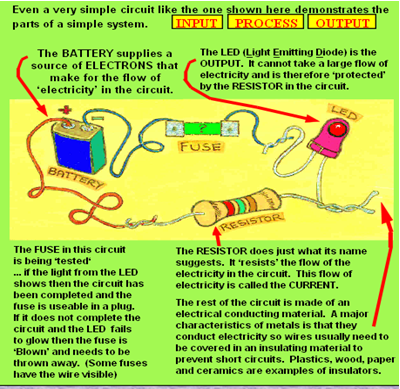
The BATTERY supplies a source of ELECTRONS that make for the flow of ‘electricity’ in the circuit.
The LED (Light Emitting Diode) is the OUTPUT. It cannot take a large flow of lectricity and is therefore ‘protected’ by the RESISTOR in the circuit.
The FUSE in this circuit is being ‘tested‘ ... if the light from the LED shows then the circuit has been completed and the fuse is useable in a plug.
If it does not complete the circuit and the LED fails to glow then the fuse is ‘Blown’ and needs to be thrown away. (Some fuses have the wire visible) .The RESISTOR does just what its name suggests. It ‘resists’ the flow of the electricity in the circuit. This flow of
electricity is called the CURRENT.
The rest of the circuit is made of an electrical conducting material.
A major characteristics of metals is that they conduct electricity so wires usually need to be covered in an insulating material to prevent short circuits. Plastics, wood, paper and ceramics are examples of insulators.
Even a very simple circuit like the one shown here demonstrates the parts of a simple system. INPUT PROCESS OUTPUT. A BUZZER or a BULB can be used as an output device but these use a lot of electricity and a battery would last only a short time. An LED however allows the battery to last much longer as it needs far less
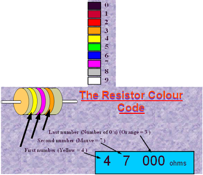
current to make it work. The unit of the supply of energy in an electrical circuit is the VOLT and the unit of resistance the OHM (W). The value of any resistor can easily be told by looking at the coloured bands around its cylindrical body.
The nearest band to one end identifies the ‘first number’, the second band identifies a ‘second number’ and a third band identifies a ‘third number’. The first number is written followed by the second number, but the third band gives the ‘number of 0’s we need to add on to those two numbers already written down.
So for example if the first number was a ‘4’ and the second a ’7’ with the third showing 3 0’s needing to be written after the first two numbers, the final value would be written as 47,000 ohms.
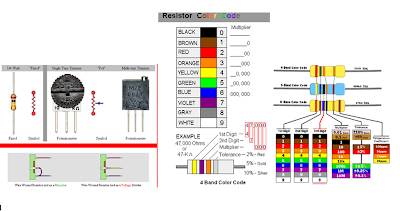
The resistor colour code can show additional information as well if extra ‘bands’ are added. The accuracy of the value for the resistor might not need to be very precise in some circuits. For instance it would not matter too much if a resistance of 900 ohms or 1100 ohms was being used in some situations and so a value of 1000 ohms (1k W) might be selected. In this situation a value of 1k W +/- 10% would be OK and this +/- figure is called the tolerance. In some uses the value must be very accurate - and clearly the more accurate a product is made the more expensive it will become.
tobe continue........

If a capacitor is polarised it has a slightly different symbol on the circuit diagram and it is marked on the case with a plus-sign (+) or a minus sign (-)
A non- polarised capacitor is shown with just two similar filled-in boxes.Think back to when you were first told about resistors and electricity and you may have been told to think in terms of water flow, perhaps from a tank or reservoir. The resistor restricts the flow of the electricity in a circuit in the same way as water is restricted when a tap is turned half-off.

Increasing the value of the resistor will lengthen the time …..or increasing the amount of charge in the capacitor (raising the value of the capacitor) could do the same thing.
CAPACITORS have values that are measured in FARADS. The FARAD is a very large unit and so more frequently capacitors have values measured in MICROFARADS ( millionths of a farad ).

So now we have a good way of getting a flow of electricity to last for a set time. We need only to adjust the resistance and allow the flow to pass through the ‘restriction’ of the resistor.
Resistor.
There is nothing too magical about each of the components that we use in electronic circuits. They each have a particular effect on the flow of electrons in a circuit. What is a ‘flow of electrons’ ? Well … that’s what the flow of electricity really is. If you’re not sure what an electron is then don’t worry just think of it as electricity. The BATTERY is a ‘supply of electrons’ and a conducting wire links one part of the circuit to the next. To prevent electrons ‘short-circuiting’ and not following the route we want, insulating material is used. If the flow of electricity needs to be restricted then RESISTORS are used.

The BATTERY supplies a source of ELECTRONS that make for the flow of ‘electricity’ in the circuit.
The LED (Light Emitting Diode) is the OUTPUT. It cannot take a large flow of lectricity and is therefore ‘protected’ by the RESISTOR in the circuit.
The FUSE in this circuit is being ‘tested‘ ... if the light from the LED shows then the circuit has been completed and the fuse is useable in a plug.
If it does not complete the circuit and the LED fails to glow then the fuse is ‘Blown’ and needs to be thrown away. (Some fuses have the wire visible) .The RESISTOR does just what its name suggests. It ‘resists’ the flow of the electricity in the circuit. This flow of
electricity is called the CURRENT.
The rest of the circuit is made of an electrical conducting material.
A major characteristics of metals is that they conduct electricity so wires usually need to be covered in an insulating material to prevent short circuits. Plastics, wood, paper and ceramics are examples of insulators.


Even a very simple circuit like the one shown here demonstrates the parts of a simple system. INPUT PROCESS OUTPUT. A BUZZER or a BULB can be used as an output device but these use a lot of electricity and a battery would last only a short time. An LED however allows the battery to last much longer as it needs far less
current to make it work. The unit of the supply of energy in an electrical circuit is the VOLT and the unit of resistance the OHM (W). The value of any resistor can easily be told by looking at the coloured bands around its cylindrical body.
The nearest band to one end identifies the ‘first number’, the second band identifies a ‘second number’ and a third band identifies a ‘third number’. The first number is written followed by the second number, but the third band gives the ‘number of 0’s we need to add on to those two numbers already written down.
So for example if the first number was a ‘4’ and the second a ’7’ with the third showing 3 0’s needing to be written after the first two numbers, the final value would be written as 47,000 ohms.
The resistor colour code can show additional information as well if extra ‘bands’ are added. The accuracy of the value for the resistor might not need to be very precise in some circuits. For instance it would not matter too much if a resistance of 900 ohms or 1100 ohms was being used in some situations and so a value of 1000 ohms (1k W) might be selected. In this situation a value of 1k W +/- 10% would be OK and this +/- figure is called the tolerance. In some uses the value must be very accurate - and clearly the more accurate a product is made the more expensive it will become.
tobe continue........

0 comments:
Posting Komentar